7 Configuration

7.1 Test Configuration

7.1.1 No hop

7.1.1.1 M2M_CFG_01

The AE manages resources on the registrar CSE (Hosting CSE)

oneM2M entities model

Figure 7.1.1.1-1: M2M_CFG_01Figure 7.1.1.1-1: M2M_CFG_01
Figure 7.1.1.1‑1: M2M_CFG_01

Figure 7.1.1.1‑1: M2M_CFG_01

7.1.1.2 M2M_CFG_02

oneM2M entities model

Figure 7.1.1.2-1: M2M_CFG_02Figure 7.1.1.2-1: M2M_CFG_02
Figure 7.1.1.2‑1: M2M_CFG_02

Figure 7.1.1.2‑1: M2M_CFG_02

7.1.1.3 M2M_CFG_10

oneM2M entities model

Figure 7.1.1.3-1: M2M_CFG_10Figure 7.1.1.3-1: M2M_CFG_10
Figure 7.1.1.3‑1: M2M_CFG_10

Figure 7.1.1.3‑1: M2M_CFG_10

NOTE: For HAIM Model tests, clause 8.5, AE1 represents a native oneM2M device that implements the HAIM models or a combined IPE(AE) plus a non-oneM2M device node (nodn).

7.1.2 Single hop

7.1.2.1 M2M_CFG_03

The AE manages resources on the remote CSE

oneM2M entities model

Figure 7.1.2.1-1: M2M_CFG_03Figure 7.1.2.1-1: M2M_CFG_03
Figure 7.1.2.1‑1: M2M_CFG_03

Figure 7.1.2.1‑1: M2M_CFG_03

7.1.2.2 M2M_CFG_04

oneM2M entities model

Figure 7.1.2.2-1: M2M_CFG_04Figure 7.1.2.2-1: M2M_CFG_04
Figure 7.1.2.2‑1: M2M_CFG_04

Figure 7.1.2.2‑1: M2M_CFG_04

7.1.2.3 M2M_CFG_05

oneM2M entities model

Figure 7.1.2.3-1: M2M_CFG_05Figure 7.1.2.3-1: M2M_CFG_05
Figure 7.1.2.3‑1: M2M_CFG_05

Figure 7.1.2.3‑1: M2M_CFG_05

7.1.2.4 M2M_CFG_08

This configuration concerns group management when the AE is using a group to fan out requests to multiple members. The connection between the AE and the Group Hosting CSE, the Group Hosting CSE and the Member Hosting CSE may be a multi hop connection following the definition in clause 7.1.3.

This configuration is mapped to cases including:

  • AE sends a request addressing /fanOutPoint in the Group Hosting CSE, the Group Hosting CSE then further fans out the request to each Member Hosting CSE.
  • The Member Hosting CSE sends a notification to the Group Hosting CSE pertaining to the subscription made through the Group Hosting CSE. The Group Hosting CSE then further aggregates the notification and sends it back to the AE.
Figure 7.1.2.4-1: M2M_CFG_08Figure 7.1.2.4-1: M2M_CFG_08
Figure 7.1.2.4‑1: M2M_CFG_08

Figure 7.1.2.4‑1: M2M_CFG_08

7.1.2.5 M2M_CFG_09

This configuration concerns device management using external technologies.

This configuration is mapped to cases including:

  • The AE sends a request addressing to IN-CSE. IN-CSE then further acts as a Management Server to send management commands to Managed Entity over the mc interface. The management command is defined in OMA DM, BBF TR069 or LWM2M.
Figure 7.1.2.5-1: M2M_CFG_09Figure 7.1.2.5-1: M2M_CFG_09
Figure 7.1.2.5‑1: M2M_CFG_09

Figure 7.1.2.5‑1: M2M_CFG_09

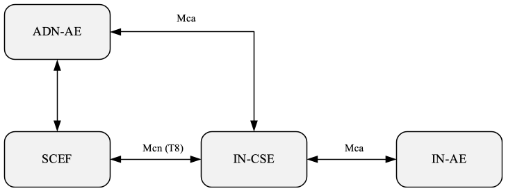
7.1.2.6 M2M_CFG_11

This configuration concerns device management using 3GPP network.

Figure 7.1.2.6-1: M2M_CFG_11Figure 7.1.2.6-1: M2M_CFG_11
Figure 7.1.2.6‑1: M2M_CFG_11

Figure 7.1.2.6‑1: M2M_CFG_11

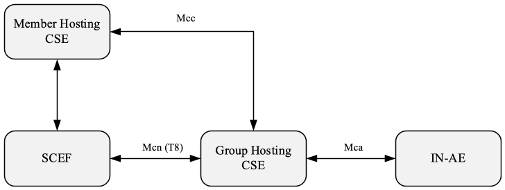
7.1.2.7 M2M_CFG_12

This configuration concerns group management when the IN-AE is using a group to fan out requests to multiple members in 3GPP interworking scenraios. The connection between the IN-AE and the Group Hosting CSE, the Group Hosting CSE and the Member Hosting CSE may be a multi hop connection following the definition in clause 7.1.3.

This configuration is mapped to cases including:

  • IN-AE sends a request addressing /fanOutPoint in the Group Hosting CSE, the Group Hosting CSE then further fans out the request to each Member Hosting CSE through 3GPP network.
Figure 7.1.2.7-1: M2M_CFG_12Figure 7.1.2.7-1: M2M_CFG_12
Figure 7.1.2.7‑1: M2M_CFG_12

Figure 7.1.2.7‑1: M2M_CFG_12

7.1.3 Multi hops

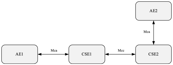
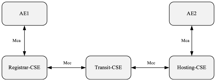
7.1.3.1 M2M_CFG_06

oneM2M entities model

Figure 7.1.3.1-1: M2M_CFG_06Figure 7.1.3.1-1: M2M_CFG_06
Figure 7.1.3.1‑1: M2M_CFG_06

Figure 7.1.3.1‑1: M2M_CFG_06

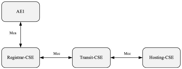
7.1.3.2 M2M_CFG_07

oneM2M entities model

Figure 7.1.3.2-1: M2M_CFG_07Figure 7.1.3.2-1: M2M_CFG_07
Figure 7.1.3.2‑1: M2M_CFG_07

Figure 7.1.3.2‑1: M2M_CFG_07