 oneM2M TS-0030Release Notes diff from v5.0.0 to v5.0.0oneM2M TS-0030Release Notes diff from v5.0.0 to v5.0.0
oneM2M supports interworking with several specific non-oneM2M solutions. Examples are: LWM2M Interworking (oneM2M TS-0014 [5]) or OIC Interworking (oneM2M TS-0024 [6]). While these examples refer to specific technologies oneM2M also allows to specify only data models - e.g. in oneM2M TS-0023: "Home Appliances Information Model and Mapping" [4] - which does not assume that a specific technology is used. The data model in oneM2M TS-0023 could e.g. be implemented with 'native' oneM2M entities like ASNs, ADNs and MNs or it could just as well be implemented in a non-oneM2M solution that is interworked with oneM2M via an Interworking Proxy Application Entity (IPE).
Ontology-based Interworking is taking an approach similar to oneM2M TS-0023, however in this case the data model is not specified but can flexibly be provided in form of an ontology. That ontology needs to be formally described (e.g. in OWL format).
Ontology-based Interworking can be used in cases where oneM2M does not provide a standardized datamodel but still interworking is desired. Such a situation may arise if e.g. a company wants to publish their proprietary datamodel for interworking purposes but does not wish to reveal their proprietary technology (radio technology, communication protocol) for data transmission.
For Ontology-based Interworking the ontology that describes the data model of the interworked technology needs to be provided in the oneM2M solution. This ontology enables the IPE to create specific resourcetypes (specializations of
From these resourcetypes oneM2M resources are created by the IPE for communication of oneM2M communicating entities with the IPE.
As with any other form of interworking, the IPE provides the translation of data in these resources into/from the external technology.
Interworking with Area Networks is accomplished in oneM2M through functionality provided by Interworking Proxy Entities (IPE).
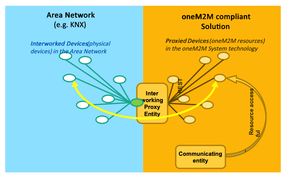

Figure 5.1.2‑1: Interworking
The IPE creates "proxied" devices as oneM2M Resources (e.g. AEs) in the oneM2M Solution that can be accessed by communicating entities (e.g. oneM2M Applications) in the usual way.
To accomplish the creation of proxied devices the IPE uses an ontology that describes the Device Information Model of the interworked Area Network and its entities (device types, their operations, etc.).
For example, in figure 5.1.2‑1, an ontology that describes a KNX Area Network and its entities would be needed.
To achieve the flexibility for the IPE to create proxied devices for many different types of Area Networks each ontology that describes a specific Device Information Model needs to be derived from the Base Ontology that is specified in [3]. This allows to specify a common scheme of mapping the classes of the ontology that describes the Device Information Model into oneM2M resources (see clause 7).
E.g. the OWL representation of an ontology that describes the Device Information Model of an Area Network of type "KNX" needs to:
NOTE: For the purpose of Ontology-based Interworking with Area Networks the Base Ontology is only used to describe type information and not for describing instances of these types. E.g. the Base Ontology describes the type "Device", but does not contain information about a specific device.The Base Ontology therefore only contains Classes and Properties but not instances. That principle needs to be followed by the ontology that describes the Device Information Model.
As explained in clause 5.1 it is the task of an IPE to interact via the Area Network with the Interworked Devices and to provide oneM2M resources (Proxied Devices) to the communicating entities for communication with the Interworked Devices. However these Proxied Devices still exhibit the native data model - the Device Information Model of the external technology of the device - and a communicating entity needs to know that native Device Information Model (e.g. ZigBee, KNX... information model).
Device abstraction relieves a communicating entity that wants to communicate with an Interworked Device (e.g. a ZigBee device) from the need to know the native Device Information Model of that Interworked Device.
Additionally to providing interworking, the IPE may translate between the - technology specific - native Device Information Model and an Abstract Information Model, that is based on of common functionalities abstracted from a set of Device Information Models. Such Abstract Information Models can be provided by industry associations of a specific industry sector.
An example of an Abstract Information Model, which is specified in oneM2M is the Home Appliance Information Model (HAIM), specified in oneM2M TS-0023 [4].
As in the case of a native Device Information Model that is used by the IPE also an Abstract Information Model can be described by an ontology and that ontology needs to be derived from the Base Ontology.
Figure 5.2.2‑1 illustrates this situation for a light switch. In the example the physical implementation is a ZigBee device implementing a ZigBee Service "On/Off Cluster". An IPE for ZigBee creates the interworking towards the ZigBee network.
To enable abstraction, this device is abstracted as oneM2M device according to the Home Appliance Information Model (HAIM). In HAIM the corresponding Service is a "binary Switch".
Both types of Services expose a Function "On Off Function" which is e.g. described in the SAREF ontology.
To turn the switch on SAREF defines an "On Command".
The corresponding Service in HAIM is executed by setting an Input Datapoint called "powerState" to the binary value "TRUE".
In Zigbee an operation (ZigBee command) needs to be invoked in the On/Off Cluster with an input parameter (ZigBee Command ID) equal to 0.
A VariableConversion can been specified in the ontology of the ZigBee Device Information Model that contains the rules how to convert a value of InputDataPoint "powerState" into a value of OperationInput "ZigBee Command ID".
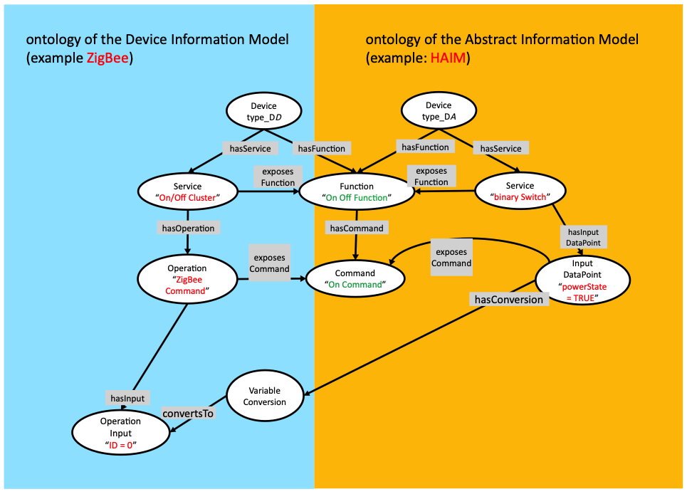

Figure 5.2.2‑1: Ontologies relations
Data flows between a communicating entity and the IPE involve oneM2M resources - specialized
NOTE 1: In this clause and in the subsequent clauses it is assumed that the communicating entity and the IPE uses the oneM2M subscribe/notify mechanism to become informed about UPDATEd resources.
It remains, however, an implementation option if subscribe/notify is used or other mechanisms (polling or other mechanisms, e.g. in case of IPE collocated/integrated in its hosting CSE) are used.
and, if the operation involves an answer (operation results). also
The following figures show the data flows for communicating with the IPE using DataPoints of a Service.
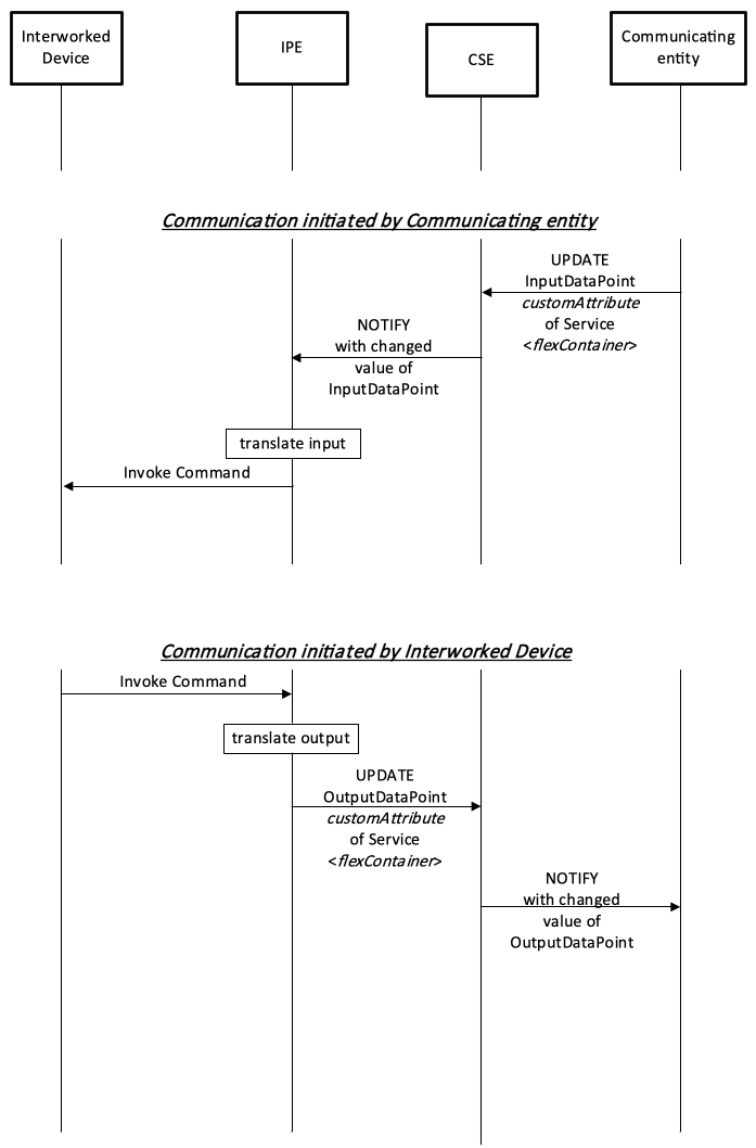

Figure 5.3.2‑1: Data flow for an IPE involving dataPoints
When a communicating entity wants to invoke a command on the Interworked Device (e.g. an actuation command), using Datapoints of the related Service:
When the Interworked Device wants to invoke a command (e.g. a reporting) on the IPE - or a subscribed communicating entity, using Datapoints of the related Service:
The following figures show the data flows for communicating with the IPE using an Operation of a Service.
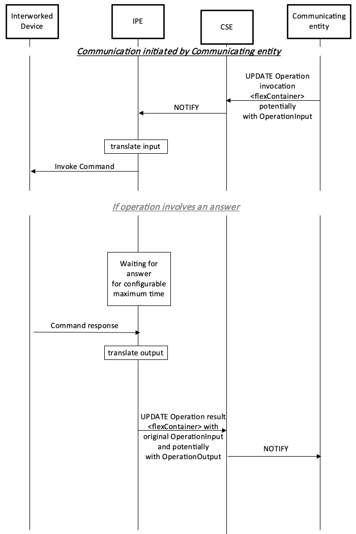

Figure 5.3.3‑1: Data flow for a translating entity involving operations when initiated by a communicating entity
In contrast to DataPoints Operations allow grouping of input- and output parameters of a Command into a single transaction between the communicating entity and the target entity. It is permissible that no OperationInput and/or OperationOutput data exist for an Operation:
If the Operation involves an (optional or mandatory) answer from the Interworked Device then: