5.2 Binding overview
5.2.1 Introduction
The MQTT protocol binding specifies how the Mca or Mcc request and response messages are transported across the MQTT protocol. Both communicating parties (AEs and CSEs) typically make use of an MQTT client library, and the communications are mediated via the MQTT server. There is no need for the client libraries or the server to be provided by the same supplier, since the protocol they use to talk to each other is defined by the MQTT specification [1].
Furthermore, the binding does not assume that the MQTT client libraries or server implementations are necessarily aware that they are being used to carry Mca, Mcc or any other oneM2M-defined primitives.
The binding is defined in terms of the MQTT protocol flows that take place between the client libraries and the MQTT server in order to effect the transport of an Mca or Mcc message.
There are two scenarios depending on the location of MQTT server: MQTT server co-located within a node, and MQTT server located independently from nodes.
5.2.2 Scenarios
5.2.2.1 MQTT server co-located scenario
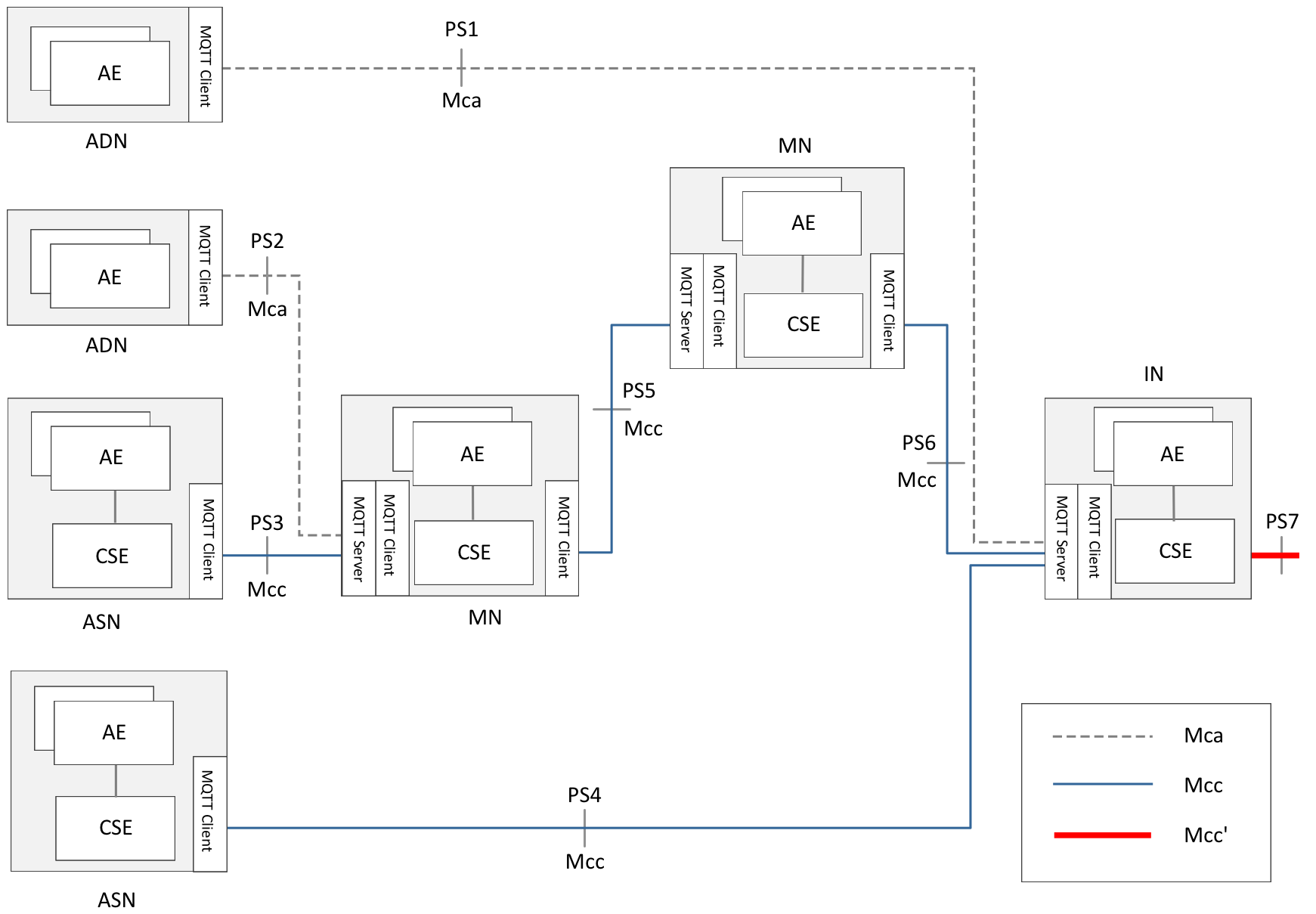
Figure 5.2.2.1-1: MQTT server co-located scenario
Figure 5.2.2.1-1 shows a protocol segment view of the MQTT server co-located scenario. In this scenario, all oneM2M nodes (ADN, ASN, MN, IN) include one or more MQTT clients. MQTT servers are provided within MN and IN.
In this scenario, the protocol segments are illustrated as follows.
Table 5.2.2.1-1: Protocol segment for MQTT server co-located scenario
|
Protocol Segment |
oneM2M Message Transported |
MQTT Interaction |
|---|---|---|
|
PS1 |
Mca (AE of ADN to CSE of IN) |
Client in ADN to Server in IN |
|
PS2 |
Mca (AE of ADN to CSE of MN) |
Client in ADN to Server in MN |
|
PS3 |
Mcc (CSE of ASN to CSE of MN) |
Client in ASN to Server in MN |
|
PS4 |
Mcc (CSE of ASN to CSE of IN) |
Client in ASN to Server in IN |
|
PS5 |
Mcc (CSE of MN to CSE of MN) |
Client in MN to Server in MN |
|
PS6 |
Mcc (CSE of MN to CSE of IN) |
Client in MN to Server in IN |
|
PS7 |
Mcc' (CSE of IN to CSE of IN) |
Client in IN to Server in IN |
5.2.2.2 MQTT server independently-located scenario
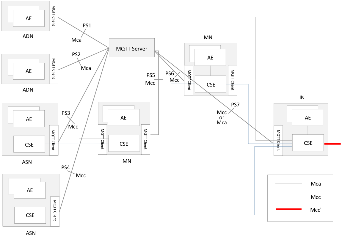
Figure 5.2.2.2-1: MQTT server independently-located scenario
Figure 5.2.2.2-1 shows a protocol segment view in which the MQTT server is located independently from the oneM2M nodes. In this scenario, all oneM2M nodes (ADN, ASN, MN, IN) include one or more MQTT clients. MQTT servers exist independently, which means the servers are located outside of the nodes.
In this scenario, the protocol segments are illustrated as follows.
Table 5.2.2.2-1: Protocol segment for MQTT server independently located scenario
|
Protocol Segment |
oneM2M Message Transported |
MQTT Interaction |
|---|---|---|
|
PS1 |
Mca (AE of ADN to CSE of IN) |
Client in ADN to Server |
|
PS2 |
Mca (AE of ADN to CSE of MN) |
Client in ADN to Server |
|
PS3 |
Mcc (CSE of ASN to CSE of MN) |
Client in ASN to Server |
|
PS4 |
Mcc (CSE of ASN to CSE of IN) |
Client in ASN to Server |
|
PS5 |
Mcc (CSE of MN to CSE of MN) |
Client in MN to Server |
|
PS6 |
Mcc (CSE of MN to CSE of MN) |
Client in MN to Server |
|
PS7 |
Mcc (CSE of IN to CSE of MN) |
Client in IN to Server |
The next four clauses show the four configurations in which the MQTT binding can be used in the co-located scenario, followed by similar configurations in the independently-located scenario.
Note
Other configurations are possible, but they are currently out of scope.
5.2.3 Configurations
5.2.3.1 AE to IN
This configuration, illustrated in figure 5.2.3.1-1, allows an AE to connect to an IN via MQTT.
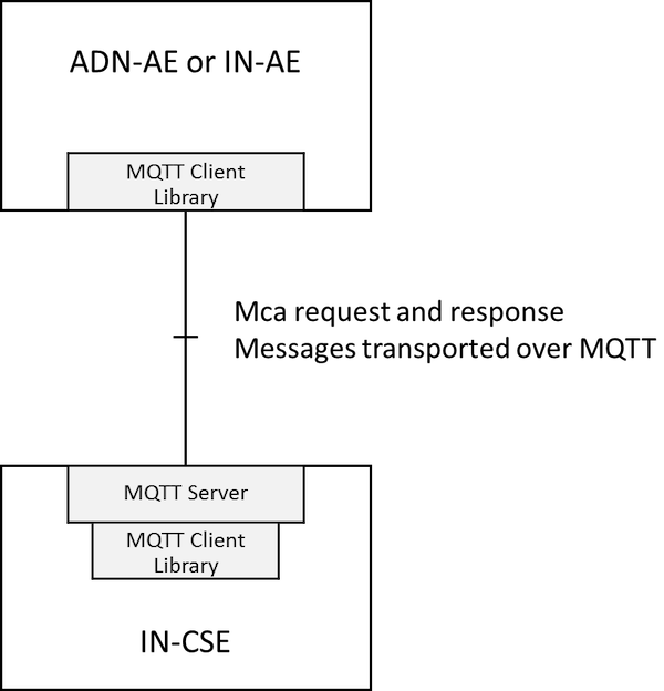
Figure 5.2.3.1-1: Using MQTT between AE and IN-CSE
The MQTT server is co-located with the IN-CSE and allows connection of the ADN-AEs (typically devices) and/or IN-AEs. It can store and forward messages if there is a gap in the connectivity with the devices. Note that the AEs each establish their own separate TCP/IP connection with the MQTT server. Thus the server shall have an accessible IP address, but AEs need not have.
5.2.3.2 AE to MN
This configuration, illustrated in figure 5.2.3.2-1, allows an ADN-AE to connect to an IN via MQTT.
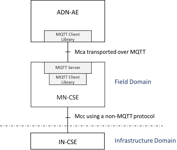
Figure 5.2.3.2-1: Using MQTT between AE and MN-CSE
This configuration is very similar to the AE-IN configuration shown in clause 5.2.3.1, except that the MQTT server is hosted on the MN rather than the IN. Onwards connection to the IN-CSE is via a different transport protocol.
5.2.3.3 MN to IN
This configuration, illustrated in figure 5.2.3.3-1, allows an MN to connect to an IN via MQTT.
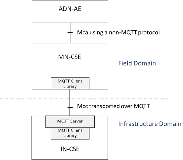
Figure 5.2.3.3-1: Mcc using MQTT between MN and IN
The MQTT server is co-located with the IN-CSE and allows connection of the MNs (typically in-field gateway boxes). It can store and forward messages if there is a gap in the connectivity with the gateways. Note that the MNs each establish their own separate TCP/IP connections with the MQTT server. Thus the server shall have an accessible IP address, but MNs need not have.
5.2.3.4 AE to MN to IN
This configuration, illustrated in figure 5.2.3.4-1, is a combination of the previous two.
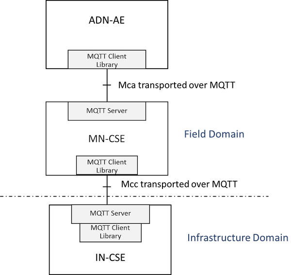
Figure 5.2.3.4-1: Mca and Mcc both using MQTT
In this configuration the two MQTT servers are independent from each other (that is to say they do not have a shared topic space). Any interactions between the ADN-AE and the IN-CSE are mediated by the MN-CSE.
5.2.3.5 AE to IN (Independent scenario)
This configuration, illustrated in figure 5.2.3.5-1, allows an AE to connect to an IN via MQTT.
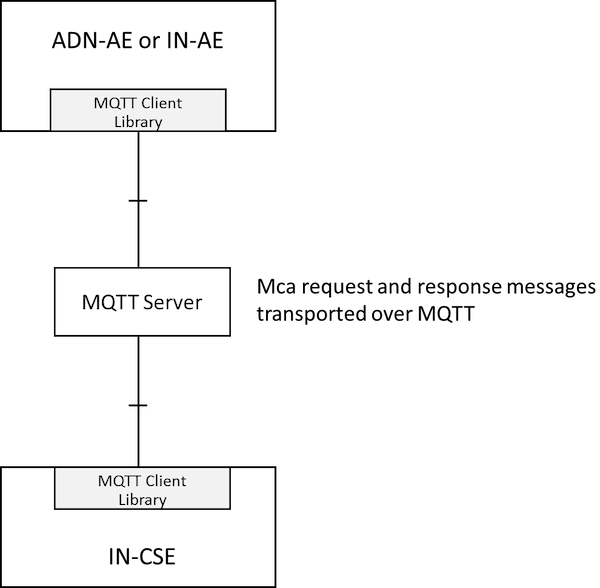
Figure 5.2.3.5-1: Using MQTT between AE and IN-CSE
The MQTT server is an independent entity, located outside of the nodes. In order to deliver Mca messages, MQTT clients within ADN-AE/IN-AE and IN-CSE connect to the MQTT server. After the clients establish TCP/IP connection with the MQTT server, Mca messages between ADN-AE/IN-AE and IN-CSE can be transported via the MQTT server.
5.2.3.6 AE to MN (Independent scenario)
This configuration, illustrated in figure 5.2.3.6-1, allows an ADN-AE to connect to an IN via MQTT.
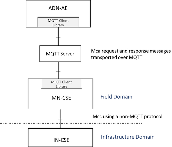
Figure 5.2.3.6-1: Using MQTT between AE and MN-CSE
In this configuration, the MQTT server is an independent entity, located outside of the nodes. MQTT clients within ADN-AE and MN-CSE are connected to the MQTT server, and the MQTT server stores and forwards the Mca messages between ADN-AE and MN-CSE. In addition, this figure shows that the onwards connection to the IN-CSE is via a different transport protocol.
5.2.3.7 MN to IN (Independent scenario)
This configuration, illustrated in figure 5.2.3.7-1, allows an MN to connect to an IN via MQTT.
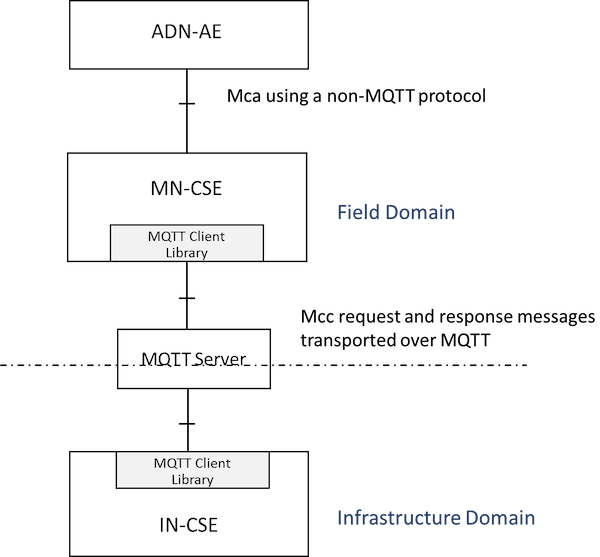
Figure 5.2.3.7-1: Mcc using MQTT between MN and IN
In this configuration, the MQTT server is an independent entity, located outside of nodes. Mcc message delivery between MN-CSE and IN-CSE are performed via the independently located MQTT server. As introduced in the previous clauses, in order to send messages, each MQTT client within MN-CSE and IN-CSE connects to the MQTT server and Mcc messages are transported via MQTT server.
5.2.3.8 AE to MN to IN (Independent scenario)
This configuration, illustrated in figure 5.2.3.8-1, is a combination of the previous two.
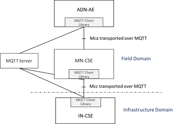
Figure 5.2.3.8-1: Mca and Mcc both using MQTT
In this configuration, the MQTT clients of ADN-AE and MN-CSE and IN-CSE connect to the independently located MQTT server. Any interactions such as Mca or Mcc message delivery among the ADN-AE and the MN-CSE and the IN-CSE are mediated by the MQTT server.