 oneM2M TS-0040Release Notes diff from v5.0.3.1 to v5.0.3oneM2M TS-0040Release Notes diff from v5.0.3.1 to v5.0.3
The present document specifies the functions for Modbus interworking in the following aspects:
In this clause, the overall resource mapping structure for exposing services between Modbus devices and oneM2M entities is introduced. Firstly, Modbus devices are modelled according to the oneM2M SDT described in oneM2M TS0023 [3]. The oneM2M SDT offers a generic and flexible modeling structure for describing functionalities of nononeM2M devices including Modbus devices. After the SDT schemas of the Modbus devices are created, they are mapped to oneM2M resources.
Each Modbus device shall be modelled as a Device component. The Modules of the Device shall be created according to the functionality of the Modbus device as defined in oneM2M TS0023 [3].
For representing data objects of a Modbus device, the mapping between a Modbus device's registers [i.2], [i.3] and SDT DataPoints is defined. Every Modbus register has the following properties: slave id, register type, address, length. The information of these registers is typically provided by a manufacturer in a device's datasheet. Register type and length are used to define the following SDT DataPoint attributes: DataType, writable, readable, and optional. The rules to perform the mapping are shown in Table 6.2.2‑1. A holding register and input register of length 2 can be mapped into either xs:integer or xs:float DataType depending on data context. As an example mapping, a coil register can be mapped to a DataPoint with DataType (xs:boolean), Readable (True), and Writable True). The optional attribute depends on a Modbus device and application logic and is supposed to be defined by the system integrator.
Table 6.2.2‑1: Mapping between Modbus register types and SDT Data points
Modbus Register
|
Mapping
|
SDT Data points
|
|||
|---|---|---|---|---|---|
Modbus register type
|
Length
|
DataType
|
Readable
|
Writable
|
|
Coil (1 bit, Read-Write)
|
1 (1 bit)
|
=>
|
xs:boolean
|
True
|
True
|
Discrete Input (1 bit, Read-Only)
|
1 (1 bit)
|
xs:boolean
|
True
|
False
|
|
Holding Register (16-bit, Read-Write) |
2 (4 bytes) |
xs:integer / xs:float
|
True
|
True
|
|
Input Register (16-bit, Read-Only) |
2 (4 bytes) |
xs:integer / xs:float
|
True
|
False
|
|
Holding Register (16-bit, Read-Write) |
1 (2 bytes) |
xs:integer
|
True
|
True
|
|
Input Register (16-bit, Read-Only) |
1 (2 bytes) |
xs:integer
|
True
|
False
|
|
Holding Register (16-bit, Read-Write) |
4 (8 bytes) |
xs:double
|
True
|
True
|
|
Input Register (16-bit, Read-Only) |
4 (8 bytes) |
xs:double
|
True
|
False
|
|
The mapping of all SDT components follows the mapping procedure defined in clause 6.2 of oneM2M TS0023 [3]. For example, the ModuleClass models shall be mapped to the specializations of <flexContainer> resource and their DataPoints to customAttributes of the corresponding <flexContainer> specializations. However, the SDT schemas do not consider interworking options with non-oneM2M Device Nodes (noDN) such as Modbus devices. For that reason, a nodnProperties attribute shall be added as a customAttribute of a <flexContainer> resource specialization which is mapped from an associated ModuleClass model.
The nodnProperties attribute stores one-to-one mappings in CSV string format [i.6] between each customAttribute of <flexContainer> resource specialization and a Modbus register with which it is associated. Each line in the nodnProperties shall contain the name of a customAttribute and associated Modbus register properties (slave id, register type, address, length). The order they are aligned is the following: customAttribute name, slave id, register type, address, length. The nodnProperties shall have one record per line and each property separated by a comma. The header line for this CSV string is mandatory and shall contain the names corresponding to the fields in the string as defined in the section 2.3 of the CSV format specification [i.6]. Table 6.2.3‑1 shows the detailed information on the fields of the nodnProperties attribute.
An example oneM2M resource schema including nodnProperties is provided in Annex B, Figure B.2.2‑2.
Table 6.2.3‑1: Fields of nodnProperties attribute
Field name
|
Type
|
Description
|
|---|---|---|
customAttribute name
|
String
|
Name of customAttribute
|
slave id
|
Integer
|
Slave id of Modbus device
|
register type
|
Enumeration
|
One of 4 register types (see Table 6.2.3‑2)
|
address
|
Integer
|
Address of the first register associated with a variable
|
length
|
Integer
|
Number of registers an associated variable occupies
|
Table 6.2.3‑2: Interpretation of register type
Value
|
Interpretation
|
|---|---|
1
|
Coil
|
2
|
Discrete input
|
3
|
Holding register
|
4
|
Input register
|
Figure 6.3‑1 shows the device registration call flow:
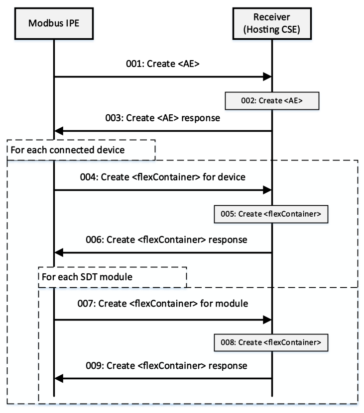

Figure 6.3‑1: Device registration call flow
The Modbus devices can accept either read or write requests from the Master. The operation to be executed is identified from the function code of a Modbus message. Therefore, the IPE needs to be able to map the oneM2M messages to Modbus messages with the appropriate function code. The function code is identified from register type of the register to be read for the read requests and from a tuple of register type and number of registers to be written (length) for the write requests.
For the read requests, the IPE shall map the register type of the register to be read to the function code according to Table 6.4‑1. For the write requests, the IPE shall map the tuple of register type and the number of registers to be written (length) to the function code according to Table 6.4‑2. Both the register type and the length along with other Modbus data needed to construct the Modbus message can be retrieved from the nodnPropertiescustomAttribute of a <flexContainer> specialization derived from a ModuleClass.
Table 6.4‑1: Register type to function code mapping for Modbus read request
Register type
|
Function code
|
|---|---|
Coil
|
01
|
Discrete input
|
02
|
Holding register
|
03
|
Input register
|
04
|
Table 6.4‑2: Register type and length to function code mapping for Modbus write request
Register type
|
Length > 1
|
Function code
|
|---|---|---|
Coil
|
false
|
05
|
Coil
|
true
|
0F
|
Holding register
|
false
|
06
|
Holding register
|
true
|
10
|
Suppose a scenario when current readings of a Modbus device need to be displayed at an AE application and Modbus-IPE continuously monitors a Modbus device and uploads that data to a CSE hosted on a server in the network. Initially, the AE shall be subscribed to the <flexContainer> resource, which is a specialization of some SDT module for a Modbus device, using a <subscription> resource (notificationEventType A, see clause 9.6.8 in oneM2M TS0001 [1]). The following steps described in Figure 6.5.1‑1 shall be performed for this scenario:
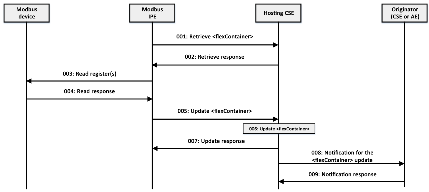

Figure 6.5.1‑1: Modbus Slave Device monitoring call flow
Suppose a scenario when it is required to update some value in a Modbus device through an AE application registered to a CSE. Initially, the Modbus IPE shall be subscribed to the <flexContainer> resource, which is a specialization of some SDT module for a Modbus device, using a blocking type of <subscription> resource (notificationEventType G, see clause 9.6.8 in oneM2M TS0001 [1]). The following steps described in Figure 6.5.2‑1 shall be performed for this scenario:
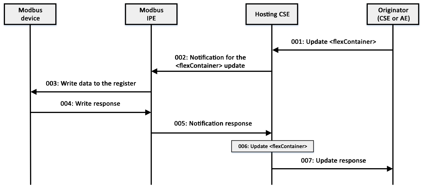

Figure 6.5.2‑1: Writing to a Modbus Slave Device call flow