oneM2M TS-0040Release Notes diff from v5.0.3.1 to v5.0.3
Annex A (informative): Introduction to Modbus
A.1 Background
Modbus was first introduced by Modicon® (now part of Schneider Electric®) for process control systems. It is used to establish master-slave/client-server communication between intelligent devices and sensors and instruments. It is a de facto standard, truly open and the most widely used network protocol in the industrial manufacturing environment.
Modbus is easy to deploy and maintain and is used across a wide range of industries. It is also an ideal protocol for Remote Terminal Unit (RTU) applications where wireless communication is required. Modbus is not only an industrial protocol. Building, infrastructure, transportation and energy applications also make use of its benefits.
Originally, Modbus was implemented as an application level protocol intended to transfer data over serial port, it has expanded to include implementations over serial, TCP/IP, and UDP. Today, it is a common protocol used by countless devices for simple, reliable, and efficient communication across a variety of networks. Modbus was designed as a request-response protocol with a flexible data and function model that are part of the reason it is still in use today. In addition, support for the simple and elegant structure of Modbus continues to grow [i.4].
A.2 Architecture and protocol stack
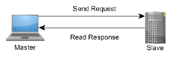
The Modbus protocol follows a master and slave architecture where a master transmits a request to a slave and waits for the response (as shown in Figure A.2‑1). This architecture gives the master full control over the flow of information, which has benefits on older multidrop serial networks. Even on modern TCP/IP networks, it gives the master a high degree of control over slave behavior, which is helpful in some designs.
Figure A.2‑1: The Master-Slave, Request-Response Relationship of Modbus device
Figure A.2‑1: The Master-Slave, Request-Response Relationship of Modbus device
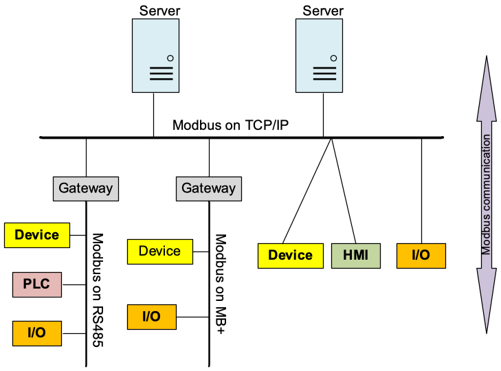
The Modbus protocol allows an easy communication within all types of networks (as shown in Figure A.2‑2). Every type of devices (such as PLC, Driver, Motion control, I/O Device, etc.) can use Modbus protocol to initiate a remote operation.
The same communication can be done as well on serial line as on an Ethernet TCP/IP network. Gateways allow a communication between several types of buses or network using the Modbus protocol [i.5].
Modbus RTU - This is used in serial communication & makes use of a compact, binary representation of the data for protocol communication. Modbus RTU is the most common implementation available for Modbus. A Modbus RTU message is transmitted continuously without inter-character hesitations.
Modbus ASCII - This is used in serial communication and makes use of ASCII characters for protocol communication.
Modbus TCP/IP or Modbus TCP - This is a Modbus variant used for communications over TCP/IP networks. It does not require a checksum calculation as lower layers already provide checksum protection.
Modbus over TCP/IP or Modbus over TCP or Modbus RTU/IP - This is a Modbus variant that differs from Modbus TCP in that a checksum is included in the payload as with Modbus RTU.
Modbus over UDP - Some have experimented with using Modbus over UDP on IP networks, which removes the overheads required for TCP.
Modbus Plus (Modbus+, MB+ or MBP) - Modbus Plus is proprietary to Schneider Electric® and unlike the other variants, it supports peer-to-peer communications between multiple masters. It requires a dedicated co-processor to handle fast HDLC-like token rotation. It uses twisted pair at 1 Mbit/s and includes transformer isolation at each node, which makes it transition/edge triggered instead of voltage/level triggered.
At present, Modbus TCP is more efficient networking through the use of dedicated connections and identifiers for each request and response. Modbus RTU and Modbus ASCII are older serial ADU formats with the primary difference between the two being that RTU uses a compact binary representation while ASCII sends all requests as streams of ASCII characters.
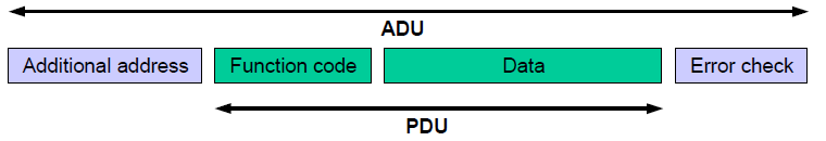
The Modbus protocol defines a simple Protocol Data Unit (PDU) independent of the underlying communication layers. The mapping of Modbus protocol on specific buses or network can introduce some additional fields on the Application Data Unit (ADU). The Modbus frame is as shown in Figure A.2‑3.
A Modbus frame or Modbus Application Data Unit (ADU) consists of the following:
Additional address field: A field containing additional addresses used by the underlying communication protocol. It is 1 byte slave address over serial links (such as RS 232, RS 485). For Modbus TCP, it is called Modbus Application Protocol (MBAP) Header that include transaction identifier, protocol identifier, length and unit identifier.
Modbus PDU: It is independent of underlying communication layer and consists of two parts: 1) 1-byte Function code to indicate identity of the requested service, 2) Variable length data field containing payload of the requested service. There are three types of Modbus PDUs: Modbus Request, Modbus Response and Modbus Exception.
An optional error check field. Modbus TCP is not needed.
A.3 Key feature
There are many devices and gateways that support Modbus, as it is a very simple protocol and convenient to transmit and understand. Specially, Modbus TCP/IP simply takes the Modbus instruction set and wraps TCP/IP around it. Development costs are exceptionally low. Minimum hardware is required, and development is easy under any operating system. The following are key features of Modbus:
Communication mode
Modbus uses master-slave/client-server communication mode, Master issues a unicast request and slave responds to that. In serial and MB+ networks, only the node assigned as the Master may initiate a command. On Ethernet, any device can send out a Modbus command, although usually only one master device does so. Modbus also supports broadcast mode where master's request is sent to all the slaves but no slave responds to broadcast request.
Data model
Modbus manages the access of data simply and flexibly. Modbus data are divided into four ranges, they are that these types of data can be provided/alterable by I/O system or an application program. In most cases, slaves store each type of data that it supports in separate memory, and limits the number of data elements that a master can access.
Function code There are three categories of Modbus Function codes, including Public Function codes, User-Defined Function codes and Reserved Function codes. Public Function codes can satisfy common operations, such as accessing data in device by reading and writing data model, and simply diagnosing device. Function code is flexibility that user can select and implement a function code by self-defining User-Defined Function codes according to service requirements.
Availability of many devices Interoperability among different vendors' devices and compatibility with a large installed base of Modbus-compatible devices makes Modbus an excellent choice.
 oneM2M TS-0040Release Notes diff from v5.0.3.1 to v5.0.3