7.10 Background Data Transfer
7.10.1 Overview
For the oneM2M system, Background Data Transfer (BDT) allows the IN-AE/CSE to have some control over its transmissions to field domain nodes that use an underlying 3GPP network that provides transfer of data in the background. Namely, the IN-AE/CSE is provided with a list of potential transfer policies (time windows, with associated maximum bit rate) and charging condition so that the IN-AE/CSE may use a time window that is more favorable in terms of tariff/cost and/or overall throughput.
For the underlying 3GPP network, management of the background data traffic for UEs (such as M2M devices) may result in significant gains for the network. For example, it is expected that for some use cases, 3rd party entities will select the more underutilized time windows to take advantage of the more favorable tariff and/or cost for the charging conditions. This effectively allows the MNO to spread the network utilization over time.
The purpose of this feature is to provide a means for the oneM2M System to inform the underlying 3GPP network of parameters that can be used for optimizing the background data traffic over the underlying 3GPP network for a set of Field Domain Nodes (Ues). Such parameters may include the expected number of UEs in the set and amount of data to be transferred a desired/preferred time window for the data transfer to these UEs, and network area information. In response, the underlying 3GPP network may inform the oneM2M system about policies that may be used to meet the given background data transfer request.
Background Data Transfer takes place in 3 steps.
- Policy Request and Selection:
- An initiating entity (AE or CSE) will provide information on the requested BDT (e.g. expected data volume per UE) for a set of Field Domain Nodes (ADN/ASN /MN) to the IN-CSE. The information will include a group or list of Field Domain Nodes that will use the policy, as well as some guidance to the IN-CSE so that it can better select from a set of potential transfer policies offered by the underlying 3GPP network.
- The IN-CSE will use the Mcn interface to provide the SCEF of the selected underlying 3GPP network with the BDT information and to ask for the Policy.
- The SCEF may provide the IN-CSE with a set of possible transfer policies for BDT and collect for charging. Using the guidance provided by the initiating Application Entity (AE) or Common Service Entity (CSE), the IN-CSE selects the transfer policy based on its own local policies, and notifies the initiating entity about the selected transfer policy.
- The IN-CSE indicates to the SCEF which policy was selected and the SCEF records the selection for charging.
- Policy Enablement:
- The IN-CSE contacts the PCRF via SCEF and enables the policy for each UE.
- Background Data Transfer:
- During the policy time window, the IN-CSE transfers the data to the UE through the 3GPP network, and based on the chosen policy.
7.10.2 Resource Structure
The <backgroundDataTransfer> resource is a child of <CSEBase>, <AE>, or <remoteCSE> and is used to request that the IN-CSE negotiates a background data transfer for a set of field nodes, with the underlying 3GPP Network. The resource attributes provide the characteristics of the background data transfer (volume per node, number of nodes), optionally a preferred time window for the transfer and geographic information, as well as the nodes that will be involved with the data transfer. Additionally, the resource also includes guidance to the IN-CSE so that it may select a transfer policy, if the underlying 3GPP network provides multiple potential transfer policies (transferSelectionGuidance).
The groupLink(s) or memberIDs attributes are used to identify the target nodes for the background data transfer request. It is assumed that the memberIDs list only includes field nodes that are UE's. If the IN-AE wishes to send the same message to a group of field domain nodes, it is assumed that the IN-AE has already created a <group> resource in the IN-CSE, with a memberIDs list that includes all field domain nodes that need to be reached through the background data transfer.
Note
The memberIDs are known when the <backgroundDataTransfer> resource is created so that the IN-CSE can determine the proper underlying 3GPP network to contact.
7.10.3 Procedures
7.10.3.1 Requesting and Selecting a Background Data Transfer Policy
Figure 7.10.3.1-1 depicts a general procedure for the request and configuration of traffic policies for BDT initiated by a request from an IN-AE. The procedure may also be initiated by a request from an MN/ASN-CSE or from the IN-CSE itself.
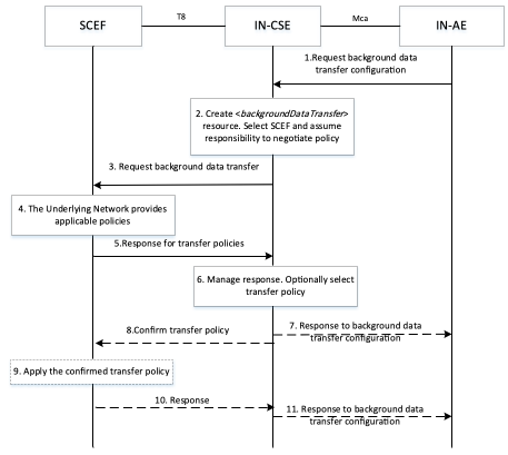
Figure 7.10.3.1-1: General Procedure for configuration of Background Data Transfer
Step 1: Request background dat a transfer configuration
An IN-AE requests IN-CSE to negotiate with SCEF in the underlying 3GPP network, to configure background data transfer, by creating a <backgroundDataTransfer> resource.
The request includes:
- the originator AE-ID of the requesting AE,
- a target identifier: i.e. the <backgroundDataTransfer> child resource of <AE>, <CSEBase> or <remoteCSE> resource.
- a set of Background Data Transfer Parameters as indicated in clause 9.6.60 of oneM2M TS-0001[1].
If the IN-CSE has received a request from an IN-AE or another Originator to create <backgroundDataTransfer> resource, it checks if the request is valid.
Step 2: IN-CSE prepares for background data transfer negotiation
IN-CSE selects the SCEF and assumes the responsibility of negotiating with the underlying 3GPP network for the background data transfer. The IN-CSE selects the SCEF based on the candidate nodes that were identified in the groupLink(s) or memberIDs list of the background data transfer request. The exact selection methods are outside the scope of this specification; however, it is expected that the external identifiers of the group members can be resolved to a SCEF.
Step 3: Request background data transfer
The IN-CSE selects the SCEF and issues a BDT request, providing Background Data Transfer parameters, to the selected SCEF for negotiating background data transfer. The fields of the API are populated as follows:
- An HTTP POST method shall be used
- URI shall be set to {apiRoot}/3gpp-bdt/v1/{scsAsId}/subscriptions/. The {apiRoot} and {scsAsId} segments are configured based on Service Provider and MNO policies.
- The request payload shall include a Bdt data structure as specified in 3GPP TS 29.122 [4] with the following attributes:
- supportedFeatures shall be set to a string value of "0"
- volumePerUE shall be set to the volume of data expected to be transferred per node, based on <backgroundDataTransfer> information.
- numberOfUEs shall be set to the expected number of nodes, based on <backgroundDataTransfer> information.
- desiredTimeWindow shall be set to the desired time window
- locationArea shall be set to the optional geographic information.
- referenceId,selectedPolicy and transferPolicies shall be absent in a BDT Request POST message.
Based on this request, if the IN-CSE is authorized, the SCEF shall negotiate the transfer policy with PCRF using the Background-Data-Transfer-Request (BTR) command over the Nt reference point as defined in 3GPP TS 29.154 [7].
Step 4: The underlying 3GPP network provides applicable policies for Background Data Transfer
The underlying 3GPP network determines one or more applicable transfer policies based on the requesting Background Data Transfer parameters.The SCEF receives the Background-Data-Transfer-Answer (BTA) on the Nt reference point as defined in 3GPP TS 29.154 [7].
Step 5: Response for transfer policies
The SCEF responds to the IN-CSE indicating the request was accepted and sends The response message as follows:
- A response code of 201 CREATED
- The URI of the Background Data resource created by the SCEF. The URI is returned in the HTTP Location header with a format of {apiRoot}/3gpp-bdt/v1/{scsAsId}/subscriptions/{subscriptionId}. The {apiRoot} and {scsAsId} segments are configured based on Service Provider and MNO policies. The {subscriptionId} segment is configured by the SCEF.
- The response payload will include a Bdt data structure as specified in 3GPP TS 29.122 [4] that includes the attributes present in the request along with the following additional attributes:
- self is configured with a URI to the Background Data resource created by the SCEF for the request
- transferPolicies containing a list of offered transfer policies, each policy including the mandatory attributes bdtPolicyId, ratingGroup and timeWindow, and the optional attributes maxUplinkBandwidth and maxDownlinkBandwidth
- referenceId may be present in the response
The IN-CSE stores locally the response referenceID and policy information received in the SCEF response, namely the transferPolicies list. See clause 8.3 for a list of possible error scenarios and error handling options for the IN-CSE.
Step 6: Process response with transfer policies provided by the underlying 3GPP network
The IN-CSE manages the SCEF response. If only one transfer policy was received from the underlying 3GPP network, the IN-CSE updates the desiredTimeWindow attribute of the <backgroundDataTransfer> resource, with the start and end time of the timeWindow attribute of the received policy. The IN-CSE also stores locally the response referenceID.
If more than one transfer policy was received from the underlying 3GPP network, the IN-CSE uses the transferSelectionGuidance and its own selection policies to select one of them. If transferSelectionGuidance is not provided, then the IN-CSE uses internal policies to select a policy. The definition of these internal policies is outside the scope of the present document.
Step 7: (Optional) Issue response to Entity initiating the background data transfer
If only one transfer policy has been received, IN-CSE responds to the original background data transfer request from the initiating entity.
Step 8: Confirm the transfer policy
If more than one transfer policy was offered in step-4, for the transfer policy selected in Step 6, the IN-CSE informs the SCEF of the selected transfer policy identifier. For this purpose, the IN-CSE shall use the PATCH request to modify the existing resource at the SCEF.
The message includes the following information.
- An HTTP PATCH method shall be used
- URI shall be set to {apiRoot}/3gpp-bdt/v1/{scsAsId}/subscriptions/{subscriptionId}. The {apiRoot} and {scsAsId} segments are configured based on Service Provider and MNO policies. The {subscriptionId} segment is configured by the SCEF.
- The request payload shall include a BdtPatch data structure as specified in 3GPP TS 29.122 [4] with the following attributes: selectedPolicy shall be set to the bdtPolicyId of the selected background data transfer policy among those contained in transferPolicies list.
Step 9: Apply the confirmed transfer policy
The transfer policy confirmed by the IN-CSE is used by SCEF to apply the configuration by notifying the underlying 3GPP network of the selected transfer policy. The SCEF includes the referenceID and bdtPolicyId of the selected policy in the Background-Data-Transfer-Request (BTR) command to PCRF over the Nt reference point as defined in 3GPP TS 29.154 [7].
As response, the SCEF receives the Background-Data-Transfer-Answer (BTA) on the Nt reference point as defined in 3GPP TS 29.154 [7].
Step 10: Response to IN-CSE
Once the underlying 3GPP network has recorded/ applied the confirmed transfer policy, the SCEF returns a response to the IN-CSE.
The message includes the following information.
- A response code of 200 OK
- The response payload will include the updated Bdt data structure as specified in 3GPP TS 29.122 [4] which includes updated selectedPolicy.
Upon receipt, the IN-CSE updates the desiredTimeWindow attribute of the <backgroundDataTransfer> resource, with the start and end time of the timeWindow attributes of the negotiated policy.
Step 11: (Optional) Issue response to Entity initiating the background data transfer
- If more than one transfer policy has been received in step 5, and step 7 has not been performed, the IN-CSE responds to the original background data transfer request from the initiating entity
See clause 8.3 for a list of possible error scenarios and error handling options for the IN-CSE.
7.10.3.2 Enabling a Background Data Transfer Policy
Figure 7.10.3.2-1 depicts a general procedure for configuring the negotiated policy in the underlying 3GPP network for the specific field domain nodes (UEs) for which the data transfer will be initiated. This is necessary as the underlying 3GPP network needs to configure its internal nodes so that these may monitor the traffic for these UEs against the negotiated policy. The procedure starts after the procedure of Section 7.10.3.1. This procedure may occur immediately after the procedure of Section 7.10.3.1 or during the time window of the selected policy.
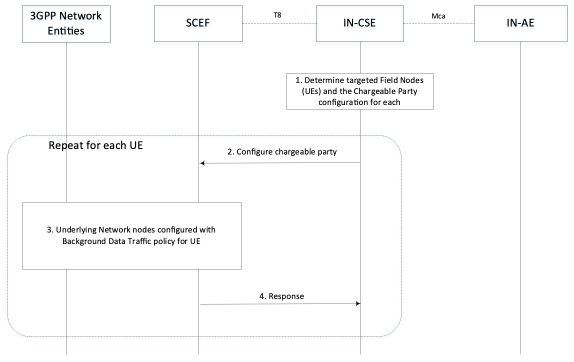
Figure 7.10.3.2-1: General Procedure for Policy Enablement
Step 1: IN-CSE determines the impacted UEs
It is assumed that prior to this procedure the IN-AE a Background Data Transfer has been requested and selected.
The <backgroundDataTransfer> resource either with a list of memberIDs, or with a link to the <group> resource that includes a list of memberIDs has been created. During the negotiation, the member list has been used by the IN-CSE to select the SCEF and a single background data transfer policy has been negotiated, for which the IN-CSE received relevant policy information e.g. the start and end time of the policy time window, the maximum aggregated authorized bandwidth for downlink transmission (in bps), and the maximum aggregated authorized bandwidth for uplink transmission (in bps).
Based on this information the IN-CSE or the initiating IN-AE may update the member list with the specific UEs for which the traffic policy enablement is to be performed (e.g. if the negotiated policy time window is different than the one requested, only a subset of the initial member list is used for performing the data transfer).
The IN-CSE uses the pointOfAccess for the entities on the member list, to obtain the IP address of the field domain nodes.
Step 2: For each UE, IN-CSE activates the selected transfer policy via the SCEF
For each UE involved in the Background Data Transfer, the IN-CSE triggers the "Change the chargeable party during the session" procedure via SCEF. The IN-CSE identifies each target UE by the IP address of the UE and provides the referenceID for the selected policy transfer to the SCEF. The request is configured as follows.
The body of the HTTP POST message shall include SCS/AS Identifier, UE IP address, Flow description, Sponsor ID, ASP ID, Sponsoring Status, time period and/or traffic volume used for sponsoring. The SCS/AS may also request to activate a previously selected policy of background data transfer by including Reference ID in the body of the HTTP POST message.
- An HTTP POST method shall be used
- URI shall be set to {apiRoot}/3gppchargeable-party/v1/{scsAsId}/transactions/. The {apiRoot} and {scsAsId} segments are configured based on Service Provider and MNO policies.
- The request payload shall include a ChargeableParty data structure as specified in 3GPP TS 29.122 [4] with the following attributes:
- supportedFeatures shall be set to a string value of "0" indicating no support for notifications via Websockets or notification test events. referenceId shall be set to referenceID of the applicable background data transfer to be applied.
- ipv4Addr shall be set to the IPv4 address (if applicable) configured in the pointOfAccess attribute of the target UE hosted ADN-AE or ASN/MN-CSE.
- ipv6Addr shall be set to the IPv6 address (if applicable) configured in the pointOfAccess attribute of the target UE hosted ADN-AE or ASN/MN-CSE.
- flowInfo shall be set to provide description of the application flows. Each flow shall include a direction (uplink or downlink), source and destination IP address, protocol, and source and destination ports. Depending on the direction of the flow, the IN-CSE shall configure a source/destination with the IP address and port and of the IN-AE initiating the background data transfer. The IN-CSE shall configure the other destination/source with the IP address and port numbers and of the UE hosted ADN-AE or ASN/MN-CSE. The IN-CSE shall configure the protocol based on the corresponding protocol binding used between the IN-AE and ADN-AE or ASN/MN-CSE.
Note
1: To meet 3GPP requirements, the IP Address of the ADN-AE or ASN/MN-CSE is a non NAT'd IP Address and Port Number.
- sponsorInformation,sponsoringEnabled shall be configured by IN-CSE as prearranged between the Service Provider and MNO. notificationDestination, requestTestNotification, websockNotifConfig are not supported by the present document.
Note
How to address the case in which referenceID is not provided in the response to the background data transfer request, is outside the scope of the current document and left to implementation.
Step 3: The network is configured by SCEF for the background data transfer
For each UE involved in the Background Data Transfer, the SCEF executes the Change the chargeable party Procedure as described in 3GPP TS 29.154 [7].
Via this procedure, the underlying 3GPP network is configured with the traffic policy information and the SCEF is informed for each UE that it has been enabled for background data transfer.
Note
The MNO will not enforce the maximum aggregated bitrate of a selected transfer policy. However, the MNO can apply offline CDRs processing to determine whether the maximum aggregated bitrate was reached.
Step 4: SCEF acknowledges policy enablement for each UE
The SCEF informs the IN-CSE that the UE has been enabled for background data transfer. If there is more than one UEs listed in memberIDs, the IN-CSE then moves onto the next UE to enable, and repeats steps 2-4.
7.10.3.3 Using Background Data Transfer Policy
- Once the transfer policy has been enabled and the time window has arrived, the initiating entity may:
- Use the fanout and group communication procedure to send the same request to each of the field domain nodes configured for background data transfer, or
- Send individual (and potentially different) requests to each of the field domain nodes configured for background data transfer.
Note
The data transfers corresponding to this step uses the Sgi interface.
7.10.3.4 Deleting a Background Data Transfer Policy
Figure 7.10.3.4.1-1 depicts a general procedure for deletion of a Background Data Transfer initiated by a request from an IN-AE. The procedure may also be initiated by a request from an MN/ASN-CSE or from the IN-CSE itself.
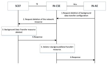
Figure 7.10.3.4-1: General Procedure for deletion of Background Data Transfer
Step 1: Request background data transfer configuration
An IN-AE requests IN-CSE to delete a <backgroundDataTransfer> resource.
The request includes:
- the originator AE-ID of the requesting AE,
- a target identifier: i.e. the <backgroundDataTransfer> child resource of <AE>, <CSEBase> or <remoteCSE> resource.
Step 2: Request deletion of the Background Data Transfer resource
The IN-CSE selects the SCEF and issues request to delete a Background Data Transfer resource at the SCEF as follows:
- An HTTP DELETE method shall be used
- URI shall be set to {apiRoot}/3gpp-bdt/v1/{scsAsId}/subscriptions/{subscriptionId}. The {apiRoot} and {scsAsId} segments are configured based on Service Provider and MNO policies. The {subscriptionId} corresponds to the one configured by the SCEF and returned to the IN-CSE when the Bdt resource was created at the SCEF.
- The request shall not contain a payload
Step 3: The SCEF deletes the Background Data Transfer resource
The underlying 3GPP network removes the applicable Background Data Transfer configuration.
Step 4: SCEF Background Data Transfer deletion
The SCEF responds with a 204 NO CONTENT indicating the request was accepted.
Step 5: The IN-CSE deletes the <backgroundDataTransfer> resource
The IN-CSE deletes the <backgroundDataTransfer> resource based on the procedure specified in clause 10.2.20.5 of oneM2M TS-0001[1].
Step 6: The IN-CSE responds to Originator
If an AE (e.g. IN-AE) was the Originator of the delete request, the IN-CSE shall return the oneM2M response primitive to the AE.